Browse categories
Explore
Fiverr Pro
English
$
USD
Power Electronics Engineer Circuit Simulation PCB Design
Are you looking for a reliable hardware engineering solution for your power conversion, battery system, or motor driver project?
Designing power electronics requires detailed. Improper trace widths, incorrect gate driver selection, or unoptimized switching frequencies can lead to thermal runaway, excessive EMI, or circuit failure.
I provide end to end power electronics design, schematic engineering, and circuit simulation to turn your requirements into reliable, production ready hardware.
What I Can Do;
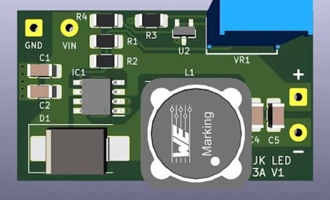
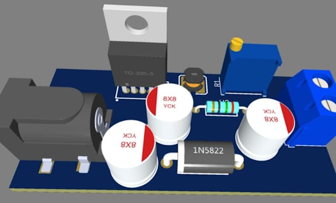
Power Conversion; DC DC Converters (Buck, Boost, Buck Boost, Flyback) and AC DC SMPS units.
Circuit Simulation & Analysis; LTspice, PSIM, or MATLAB/Simulink modeling for transient behavior, stability, and thermal limits.
Battery Systems; Custom BMS, battery protection, and charging circuits.
PCB Engineering; High current trace sizing, thermal via placement, copper pour planning, and clearance/creepage spacing for high voltage isolation.
Deliverables;
Schematic files
Complete SPICE simulation model
Bill of Materials (BOM)
Manufacturing output files.
please send a message with your input/output voltage, current requirements, and mechanical constraints before order.
What details do I need to provide before ordering?
Please provide input voltage range, target output voltage/current, efficiency goals, operating environment, and preferred EDA software (Altium, KiCad, or EasyEDA).
Which EDA software tools do you support for schematics and PCB layout?
Schematics and layouts can be delivered in Altium Designer, KiCad, or EasyEDA based on your workflow requirement.
In what format will I receive the circuit simulations?
Simulations are delivered as executable LTspice (.asc) or PSIM source files alongside exported PDF/PNG waveform plots.
Do you provide manufacturing-ready files for PCB fabrication?
Yes. Premium packages include Gerber files (RS-274X), NC Drill files, Pick and Place files (CPL), and 3D STEP models ready for JLCPCB, PCBWay, or other fabrication houses.
How do you handle thermal management and trace sizing for high currents?
Trace widths and copper weights are calculated based on IPC-2221 standards. High-power designs incorporate copper fills, thermal vias, and heatsink mounting footprints.
What if my power design requires custom firmware or microcontrollers?
Firmware for digital power control (e.g., STM32 or TI C2000 PWM generation) is handled via custom offers based on your control loop requirements.
How are revisions handled during the design process?
Revisions cover adjustments within the original scope (e.g., tweaking component footprints, adjusting component tolerance, or updating layout clearances).
Can you design circuits that comply with safety and EMI standards?
Designs account for high-voltage clearance/creepage rules and low-EMI switching loop practices. However, physical compliance testing (CE/UL/FCC) must be performed on your fabricated hardware.